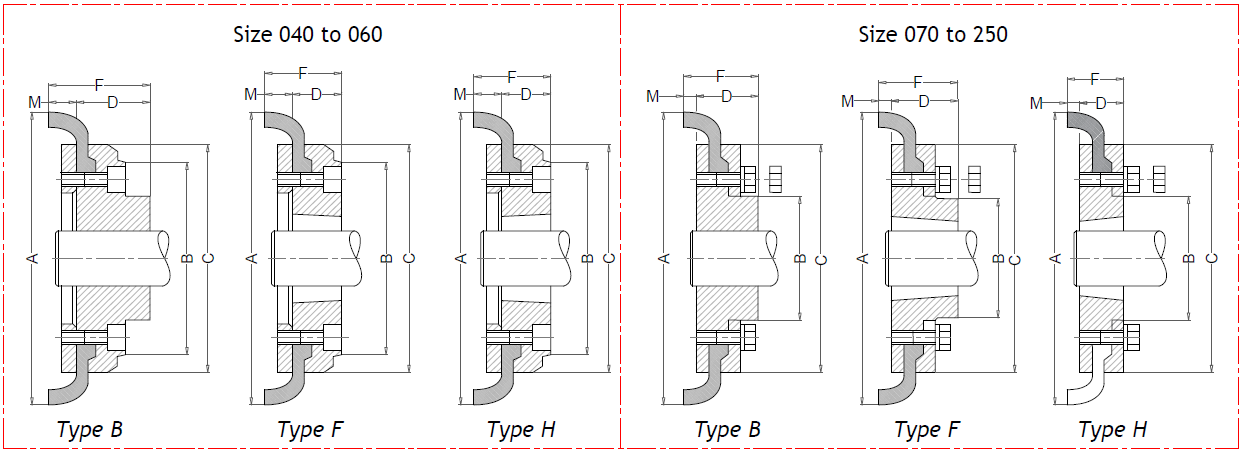
| Coupling Size |
Bush Size |
Max Bore |
Pilot Bore |
|
|
|
|
Types F & H |
Type B |
Weight# kg |
| Metric |
Inch |
A |
B |
C |
M * |
F |
D |
F |
D |
| 040B |
- |
32 |
- |
12 |
104 |
- |
82 |
11.0 |
- |
- |
33 |
22 |
0.84 |
| 040F |
1008 |
25 |
1" |
- |
104 |
- |
82 |
11.0 |
33.0 |
22 |
- |
- |
0.84 |
| 040H |
1008 |
25 |
1" |
- |
104 |
- |
82 |
11.0 |
33.0 |
22 |
- |
- |
0.84 |
| 050B |
- |
38 |
- |
15 |
133 |
79 |
100 |
12.5 |
- |
- |
45 |
32.5 |
1.26 |
| 050F |
1210 |
32 |
1.1/4" |
- |
133 |
79 |
100 |
12.5 |
37.5 |
25 |
- |
- |
1.26 |
| 050H |
1210 |
32 |
1.1/4" |
- |
133 |
79 |
100 |
12.5 |
37.5 |
25 |
- |
- |
1.26 |
| 060B |
- |
45 |
- |
18 |
165 |
103 |
124.5 |
16.5 |
- |
- |
55 |
38.5 |
2.10 |
| 060F |
1610 |
42 |
1.5/8" |
- |
165 |
103 |
124.5 |
16.5 |
41.5 |
25 |
2.10 |
| 060H |
1610 |
42 |
1.5/8" |
- |
165 |
103 |
124.5 |
16.5 |
41.5 |
25 |
2.10 |
| 070B |
- |
50 |
- |
22 |
187 |
80 |
142 |
11.5 |
- |
- |
46.5 |
35 |
3.26 |
| 070F |
2012 |
50 |
2" |
- |
187 |
80 |
142 |
11.5 |
44.5 |
33 |
- |
- |
3.26 |
| 070H |
1610 |
42 |
1.5/8" |
- |
187 |
80 |
142 |
11.5 |
42.5 |
31 |
- |
- |
3.15 |
| 080B |
- |
60 |
- |
25 |
211 |
98 |
165 |
12.5 |
- |
- |
55 |
42.5 |
5.15 |
| 080F |
2517 |
65 |
2.1/2" |
- |
211 |
98 |
165 |
12.5 |
58.5 |
46 |
- |
- |
5.15 |
| 080H |
2012 |
50 |
2" |
- |
211 |
98 |
165 |
12.5 |
45.5 |
33 |
- |
- |
4.83 |
| 090B |
- |
70 |
- |
28 |
235 |
108 |
187 |
13.5 |
- |
- |
63.5 |
50 |
7.46 |
| 090F |
2517 |
65 |
2.1/2" |
- |
235 |
108 |
187 |
13.5 |
59.5 |
46 |
- |
- |
7.35 |
| 090H |
2517 |
65 |
2.1/2" |
- |
235 |
108 |
187 |
13.5 |
59.5 |
46 |
- |
- |
7.35 |
| 100B |
- |
80 |
- |
32 |
254 |
120 |
214 |
13.5 |
- |
- |
70.5 |
57 |
10.4 |
| 100F |
3020 |
75 |
3" |
- |
254 |
120 |
214 |
13.5 |
65.5 |
52 |
- |
- |
10.4 |
| 100H |
2517 |
65 |
2.1/2" |
- |
254 |
120 |
214 |
13.5 |
59.5 |
46 |
- |
- |
9.87 |
| 110B |
- |
90 |
- |
30 |
279 |
134 |
232 |
12.5 |
- |
- |
70.5 |
58 |
13.1 |
| 110F |
3020 |
75 |
3" |
- |
279 |
134 |
232 |
12.5 |
64.5 |
52 |
- |
- |
12.3 |
| 110H |
3020 |
75 |
3" |
- |
279 |
134 |
232 |
12.5 |
64.5 |
52 |
- |
- |
12.3 |
| 120B |
- |
100 |
- |
38 |
314 |
143 |
262 |
14.5 |
- |
- |
84.5 |
70 |
17.7 |
| 120F |
3525 |
100 |
4" |
- |
314 |
140 |
262 |
14.5 |
80.5 |
66 |
- |
- |
17.3 |
| 120H |
3020 |
75 |
3" |
- |
314 |
140 |
262 |
14.5 |
66.5 |
52 |
- |
- |
16.7 |
| 140B |
- |
130 |
- |
75 |
359 |
178 |
313 |
16.0 |
- |
- |
110 |
94 |
23.3 |
| 140F |
3525 |
100 |
4" |
- |
359 |
178 |
313 |
16.0 |
82.0 |
66 |
- |
- |
23.4 |
| 140H |
3525 |
100 |
4" |
- |
359 |
178 |
313 |
16.0 |
82.0 |
66 |
- |
- |
23.4 |
| 160B |
- |
140 |
- |
75 |
402 |
197 |
347 |
15.0 |
- |
- |
117 |
102 |
37.6 |
| 160F |
4030 |
115 |
4.1/2" |
- |
402 |
197 |
347 |
15.0 |
92.4 |
77.4 |
- |
- |
34.1 |
| 160H |
4030 |
115 |
4.1/2" |
- |
402 |
197 |
347 |
15.0 |
92.4 |
77.4 |
- |
- |
34.1 |
| 180B |
- |
150 |
- |
75 |
470 |
205 |
396 |
23.0 |
- |
- |
137 |
114 |
51.6 |
| 180F |
4535 |
125 |
5" |
- |
470 |
205 |
396 |
23.0 |
112.0 |
89 |
- |
- |
44.3 |
| 180H |
4535 |
125 |
5" |
- |
470 |
205 |
396 |
23.0 |
112.0 |
89 |
- |
- |
44.3 |
| 200B |
- |
150 |
- |
85 |
508 |
206 |
433 |
24.0 |
- |
- |
138 |
114 |
61.1 |
| 200F |
4535 |
125 |
5" |
- |
508 |
206 |
433 |
24.0 |
113.0 |
89 |
- |
- |
56.3 |
| 200H |
4535 |
125 |
5" |
- |
508 |
206 |
433 |
24.0 |
113.0 |
89 |
- |
- |
56.3 |
| 220B |
- |
160 |
- |
85 |
562 |
224 |
472 |
27.5 |
- |
- |
154.5 |
127 |
83.6 |
| 220F |
5040 |
125 |
5" |
- |
562 |
224 |
472 |
27.5 |
129.5 |
102 |
- |
- |
75.6 |
| 220H |
5040 |
125 |
5" |
- |
562 |
224 |
472 |
27.5 |
129.5 |
102 |
- |
- |
75.6 |
| 250B |
- |
190 |
- |
88 |
628 |
254 |
532 |
28.5 |
- |
- |
160.5 |
132 |
109.0 |
| 250F |
5040 |
125 |
5" |
- |
628 |
254 |
532 |
28.5 |
155.5 |
127 |
- |
- |
106.0 |
| 250H |
5040 |
125 |
5" |
- |
628 |
254 |
532 |
28.5 |
155.5 |
127 |
- |
- |
106.0 |
# = Is the weight for a half coupling.
* = M is half the distance between flange faces
Flanges up to size 180 are produced from forged C45 steel. From size 200 upwards are produced from GGG.


